PRIMARY Equations
Scintillating Photovoltaics: Measuring Radiation-to-Electric Energy Conversion Efficiency
Simulation Equations By Team ElectroSynthesis
X-ray Attenuation in Scintillator
1. Beer-Lambert Law
The transmitted X-ray intensity through the scintillator:
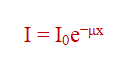
I0 = initial intensity
μ = linear attenuation coefficient (dependent on material and photon energy)
x = scintillator thickness
2. Attenuation Coefficient Components
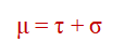
τ = photoelectric absorption
σ = Compton scattering
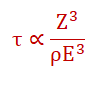
Z = atomic number
ρ = density
E = energy of a photon
Compton Scattering dominates at higher energies and lower Z.
Scintillator Light Emission and Escape
1. Optical Photon Yield
The number of optical photons generated per X-ray interaction:
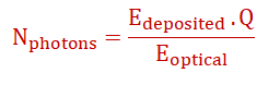
Q = scintillator’s quantum efficiency
Eoptical = average energy per optical photon
2. Depth-Dependent Escape Efficiency
The fraction of optical photons escaping the scintillator depends on interaction depth z:
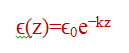
ϵ0 = surface escape efficiency
k = an absorption coefficient for the scintillator material
3. Swank Factor
Quantifies light-yield variance due to depth-dependent escape:
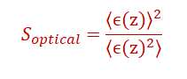
A lower Swank factor implies higher noise.
Photon Absorption in Perovskite Cell
1. Absorption Coefficient
The fraction of photons absorbed in the perovskite layer:
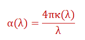
κ(λ) = extinction coefficient at wavelength λ
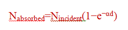
2. Lambertian Absorption
The absorbed photon flux in a perovskite layer of thickness d:
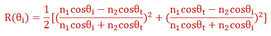
3. Reflection Losses
For normal incidence, reflection at a material boundary is:
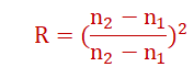
n1, n2 = refractive indices of adjacent layers
Monte Carlo Components
1. X-ray Transport
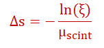
Path length sampling (Exponential distribution):
For each X-ray photon:
ξ∼U(0,1) is a uniform random variable.
Interaction type selection:
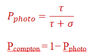
Pcompton = 1− Pphoto
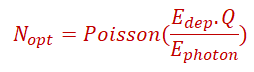
2. Optical Photon Generation
Number of optical photons:
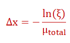
3. Photon Transport in Scintillator
Step size calculation:
Boundary handling (Fresnel reflection):
SECONDARY Equations
1. Beam & Dose Characterization
Beam Particle Rate (R_beam):
Number of particles per second hitting your detector area.
Source: Directly from DESY beam instrumentation (e.g., counters, intensity monitors) potentially scaled by your collimator acceptance.
Units: particles/second
Beam Flux (Φ):
Particle rate per unit area.
Φ = R_beam / A_coll
Variables:
R_beam: Beam particle rate (particles/s)
A_coll: Area of collimator aperture (e.g., cm² or m²)
Units: particles / (cm² ⋅ s) or particles / (m² ⋅ s)
Average Energy Deposited per Electron in Scintillator (⟨ΔE_dep⟩):
This is the average energy lost by a single beam electron via ionizing collisions within the scintillator thickness.
⟨ΔE_dep⟩ ≈ (dE/dx)_coll * ρ_scint * Δx_scint
Variables:
(dE/dx)_coll: Collision Stopping Power of the electron in the scintillator material at the beam energy (MeV⋅cm²/g or J⋅m²/kg). Source: Simulation (Geant4) or Literature Database (NIST PSTAR/ESTAR).
ρ_scint: Density of the scintillator material (g/cm³ or kg/m³).
Δx_scint: Thickness of the scintillator along the beam path (cm or m).
Units: MeV or Joules (J)
Note: This is an average; actual energy deposition has fluctuations (Landau distribution).
Deposited Power Rate in Scintillator (P_dep):
Rate at which energy is deposited by the beam in the scintillator volume defined by the collimator.
P_dep = R_beam * ⟨ΔE_dep⟩
Units: MeV/s or Watts (W) (1 MeV/s = 1.602 × 10⁻¹³ W)
Total Particle Fluence (F):
Total number of particles per unit area accumulated during irradiation.
F = Φ * t_exposure
Variables:
t_exposure: Duration of the radiation hardness exposure (s).
Units: particles/cm² or particles/m²
Estimated Absorbed Dose (D):
Energy absorbed per unit mass, relevant for radiation damage.
D ≈ F * [(dE/dx)_coll / ρ_scint] = F * S_col
Variables:
S_col = (dE/dx)_coll / ρ_scint: Mass Collision Stopping Power (MeV⋅cm²/g or J⋅m²/kg).
Units: Gray (Gy = J/kg) or rad (1 Gy = 100 rad).
Note: Accurate dose calculation requires careful consideration of units and potentially simulation. DESY staff might provide dose estimates based on beam conditions and material.
2. Photovoltaic (PV) Cell Characterization (from I-V Curves)
Measured Parameters (from SMU):
Voltage (V) across the PV cell.
Current (I) flowing from the PV cell.
An I-V curve is a plot of I vs. V.
Key I-V Parameters:
Open-Circuit Voltage (V_oc): Voltage where I = 0. Read directly from the I-V curve.
Short-Circuit Current (I_sc): Current where V = 0. Read directly from the I-V curve.
Power (P): P = V * I.
Calculated for each point on the I-V curve.
Maximum Power Point (MPP): The point (V_mp, I_mp) on the I-V curve where P is maximum. Found by finding the maximum of the P vs. V curve.
Maximum Power (P_max):
P_max = V_mp * I_mp.
Fill Factor (FF): A measure of the "squareness" of the I-V curve.
FF = P_max / (V_oc * I_sc) = (V_mp * I_mp) / (V_oc * I_sc)
Units: Dimensionless (typically between 0.5 and 0.85).
Ideality Factor (n): Describes how closely the diode follows the ideal diode equation. Extracted from the slope of the I-V curve in the region dominated by diode current (often near V_oc).
Simplified Diode Equation:
I ≈ I₀ * [exp(qV / (n * k_B * T)) - 1] - I_L (where I_L ≈ I_sc)
Extraction Method:
In the dark or under illumination near V_oc (where exp term dominates and V > few * nk_BT/q), the equation simplifies. One common method involves plotting ln(I + I_sc) vs V (for V near V_oc) or ln(I) vs V for dark current at sufficient forward bias. The slope (m) of the linear region is related to n:
m = d(ln(I_diode))/dV ≈ q / (n * k_B * T)
n ≈ q / (m * k_B * T)
Variables:
q: Elementary charge (1.602 × 10⁻¹⁹ C)
k_B: Boltzmann constant (1.381 × 10⁻²³ J/K or 8.617 × 10⁻⁵ eV/K)
T: Temperature in Kelvin (K). Measured using your temperature sensor.
Units: Dimensionless (typically between 1 and 2 for solar cells).
3. Scintillation & Light Collection (Conceptual / Simulation Based)
Average Generated Scintillation Photons per Electron (⟨N_gen⟩):
⟨N_gen⟩ ≈ ⟨ΔE_dep⟩ * Light_Yield
Variables:
Light_Yield: Photons generated per unit energy deposited (photons/MeV). Source: Literature or scintillator datasheet.
Units: photons/electron
Light Collection & Detection Efficiency (LCDE):
Fraction of generated photons that result in a detected signal (electron-hole pair) in the PV cell.
LCDE = (Number of Detected Photons) / (Number of Generated Photons)
4. Energy Storage (Supercapacitor)
Stored Energy (E_stored):
E_stored = 0.5 * C * V_sc²
Variables:
C: Capacitance of the supercapacitor (Farads, F). Source: Datasheet.
V_sc: Voltage across the supercapacitor (Volts, V). Measured over time.
Units: Joules (J)
Average Charging Power (P_charge_avg):
P_charge_avg = ΔE_stored / Δt = [0.5 * C * V_final² - 0.5 * C * V_initial²] / Δt
Variables:
V_final, V_initial: Final and initial voltages over the time interval Δt.
Units: Watts (W)
5. Overall Energy Conversion Efficiency (η)
Definition : Electrical power output from the PV cell relative to the rate of energy deposition by the beam in the scintillator.
η = P_max / P_dep = P_max / (R_beam * ⟨ΔE_dep⟩)
Units: Dimensionless.
Note: Ensure P_max (W) and P_dep (W) are in consistent units. This efficiency factor includes scintillation efficiency, light collection, PV quantum efficiency, and PV electrical performance (FF). It represents the efficiency of the entire chain from energy deposited by the primary beam electron in the scintillator to maximum electrical power output.
6. Radiation Damage Quantification
Percentage Change (%Δ):
For any PV parameter (Param = V_oc, I_sc, FF, P_max):
%ΔParam = [(Param_after - Param_before) / Param_before] * 100%
Plot %ΔParam vs. Fluence (F) or Dose (D)